I put off finishing making a wooden box for years. The parts, four panels and a sheet of panel ply have been at my workbench for ages, but I have waited to finish the box because I couldn’t figure out how to convert my table saw’s useless miter (T-bar) into a finger joint jig. More on that later.
The solution I arrived at was to build a short cross-cut sled, and then use my 3D printer to make the alignment pin and a jig to glue it in place. I’m relying on the 3D printer for precision and making a very small part, and I made two design choices for the cross-cut sled. The first design choice was to use thin sheet goods for the base of the sled to help ensure the squareness of the table saw was not compromised by any twist and warping in the main board. The second was to use adhesive and the edge of the tablesaw to ensure the alignment was square.
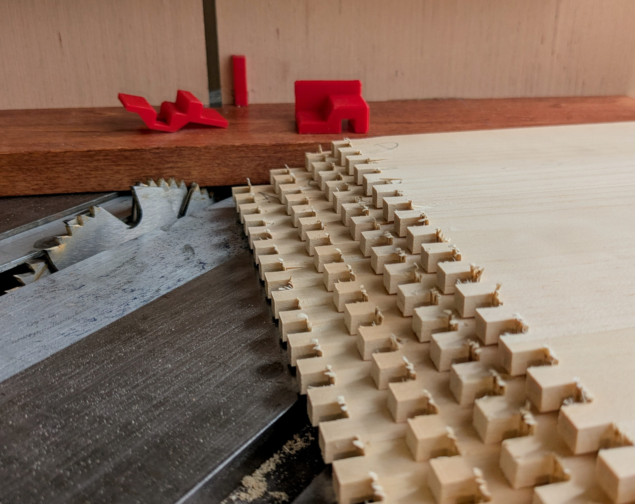
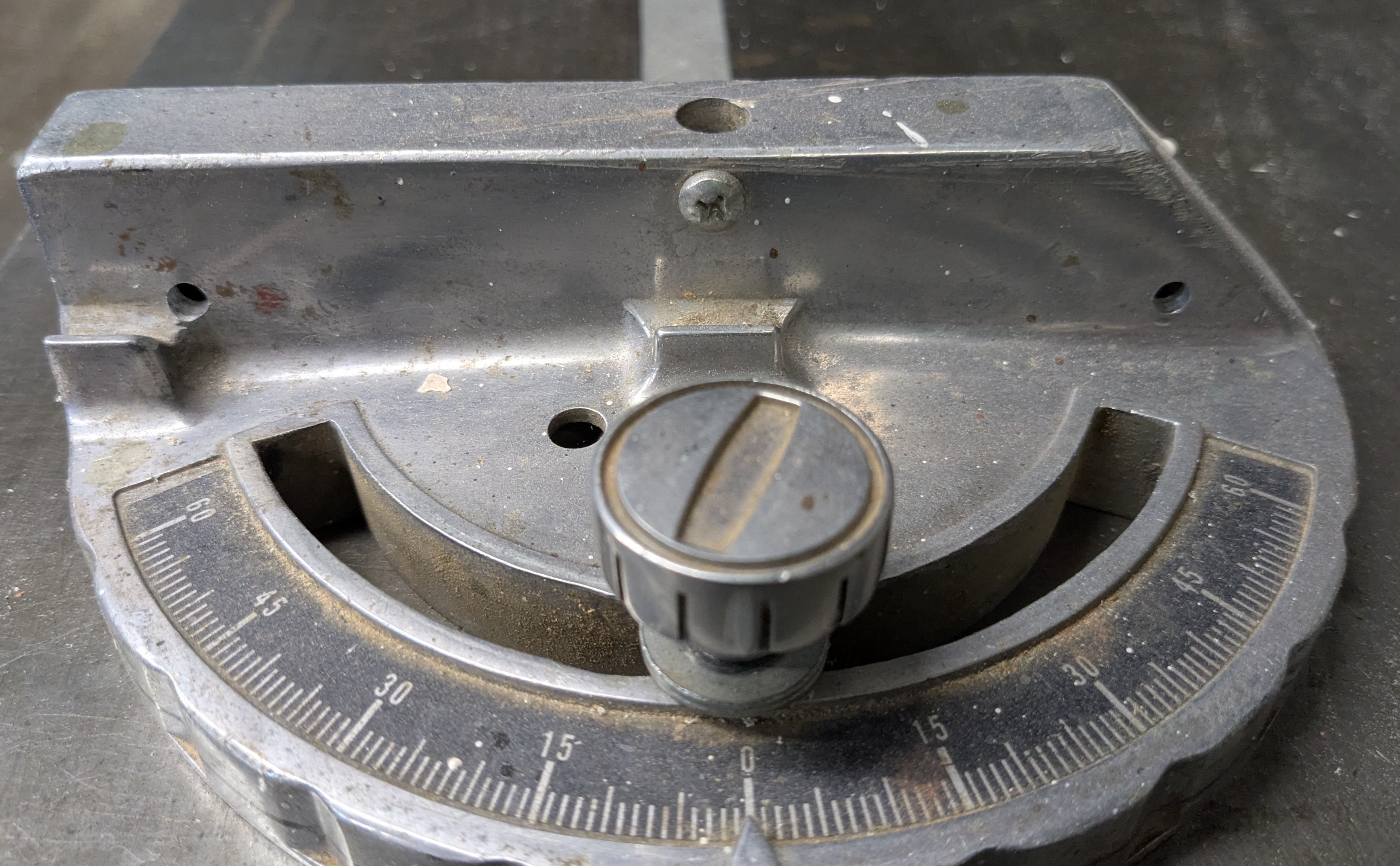
Just to be clear, I have one of the best table saws made by the insane in distant past. In fact, my table saw model make a cameo appearance in the Wierd Al movie UHF, screencap provided to help you remember the delightful madcap plot. I’m chuckling inside, but I really should replace this thing. It’s sad, but notice the gigantic dip to the throat plate. That’s real. Sigh.

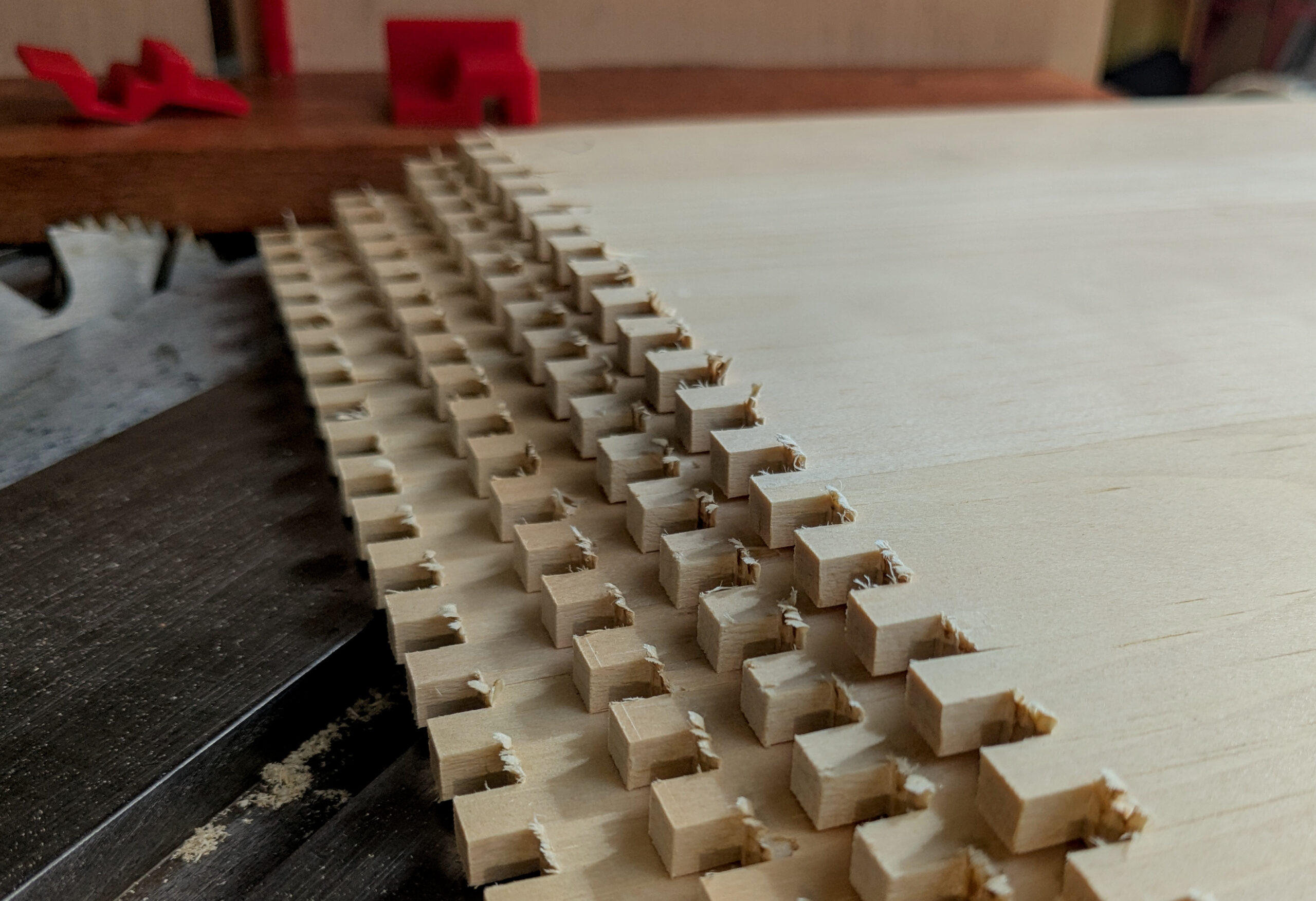
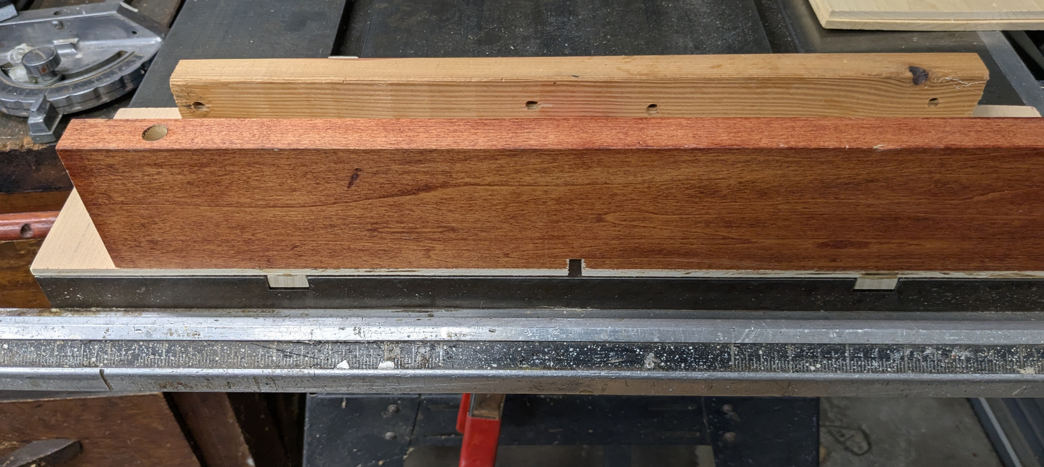
The solution to try to get the best result from this that I can is the same as for any table saw, jigs and stability. The finger joint can be cut entirely on the table saw, basically by cutting the a slot and then putting that slot over guide finger and cutting the next slot and then indexing down. The problem in making such a jig is getting the pin size correct and then getting the distance from the blade to the pin to be the same. I solved that with a single parameter FreeCAD draft. You can get the printer files I used and the FreeCAD for parametric control at Printables.
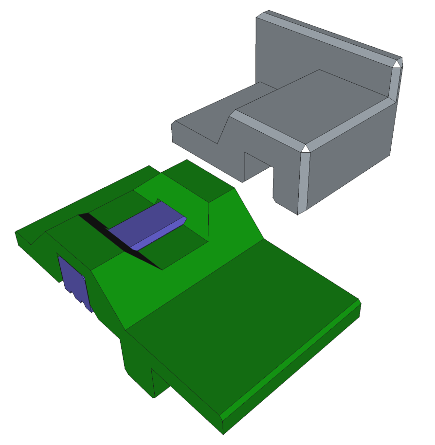
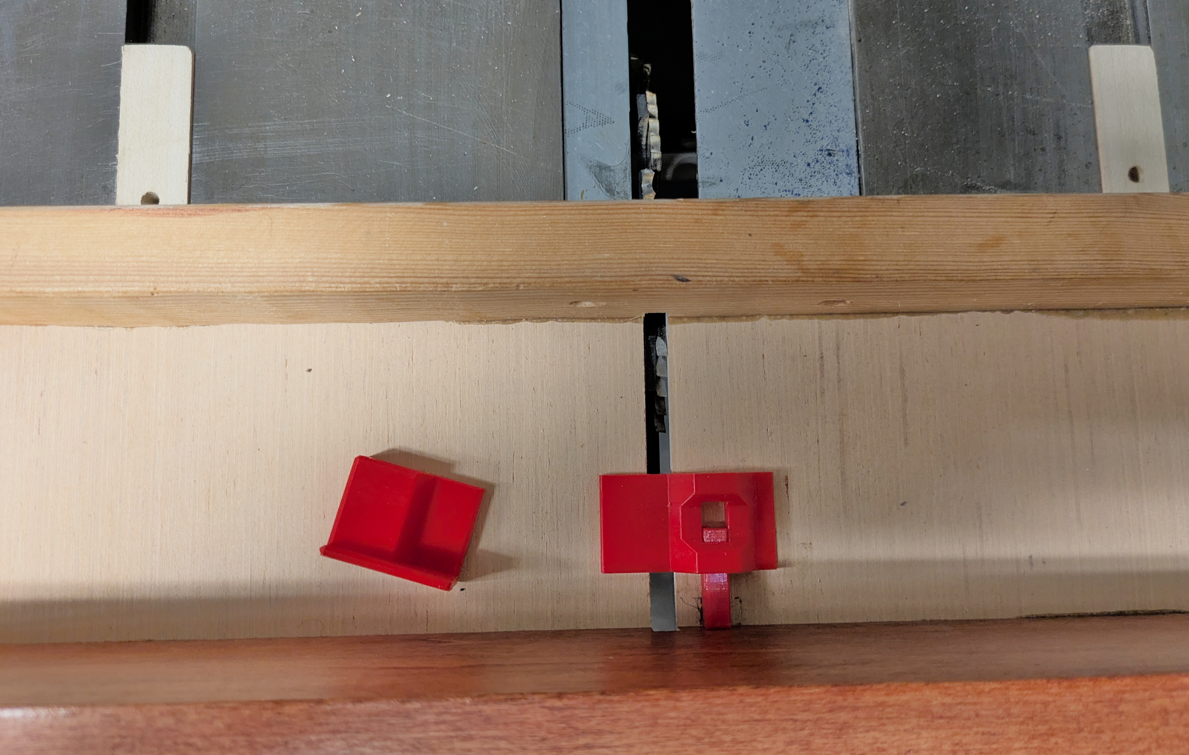
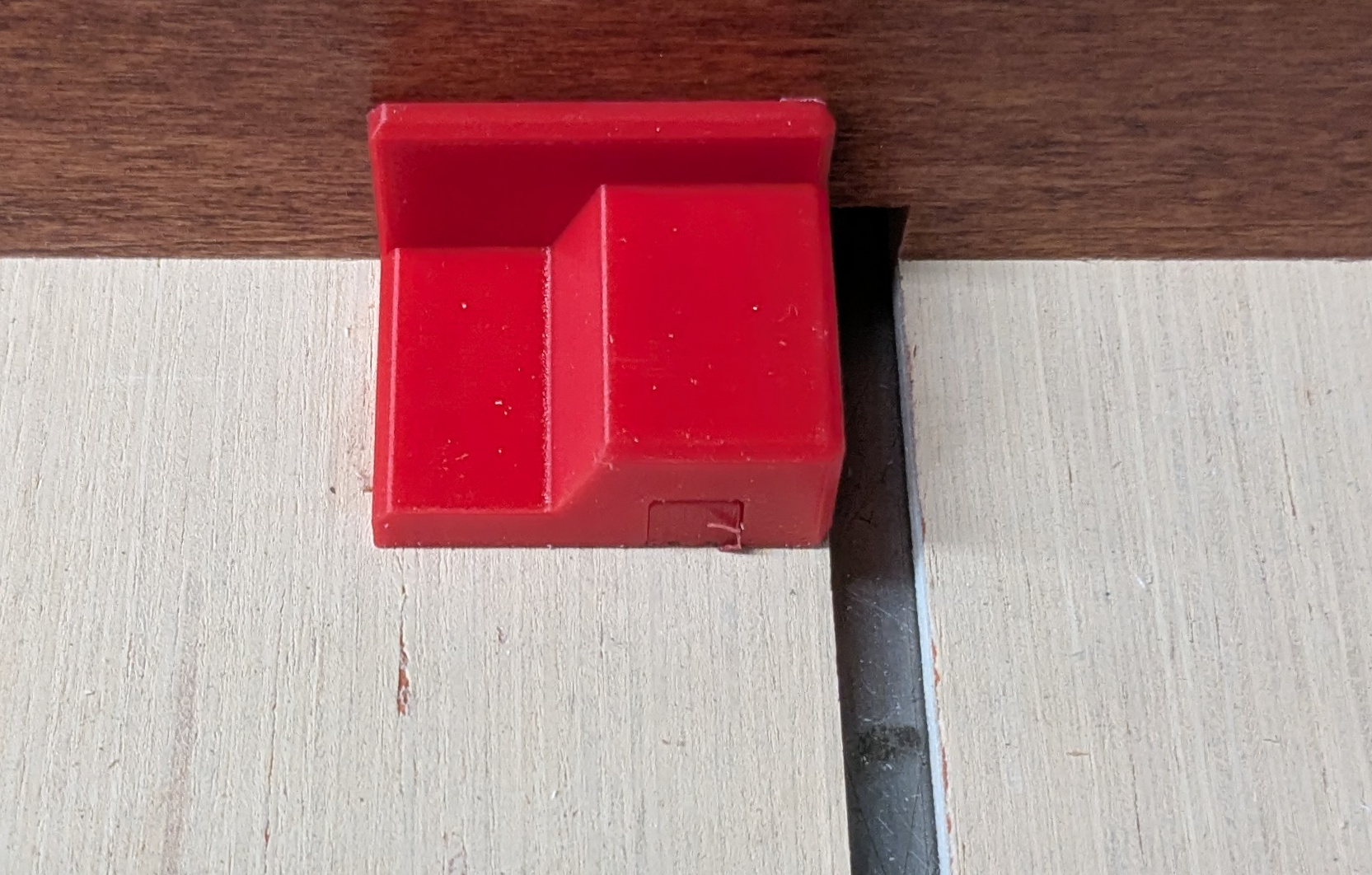
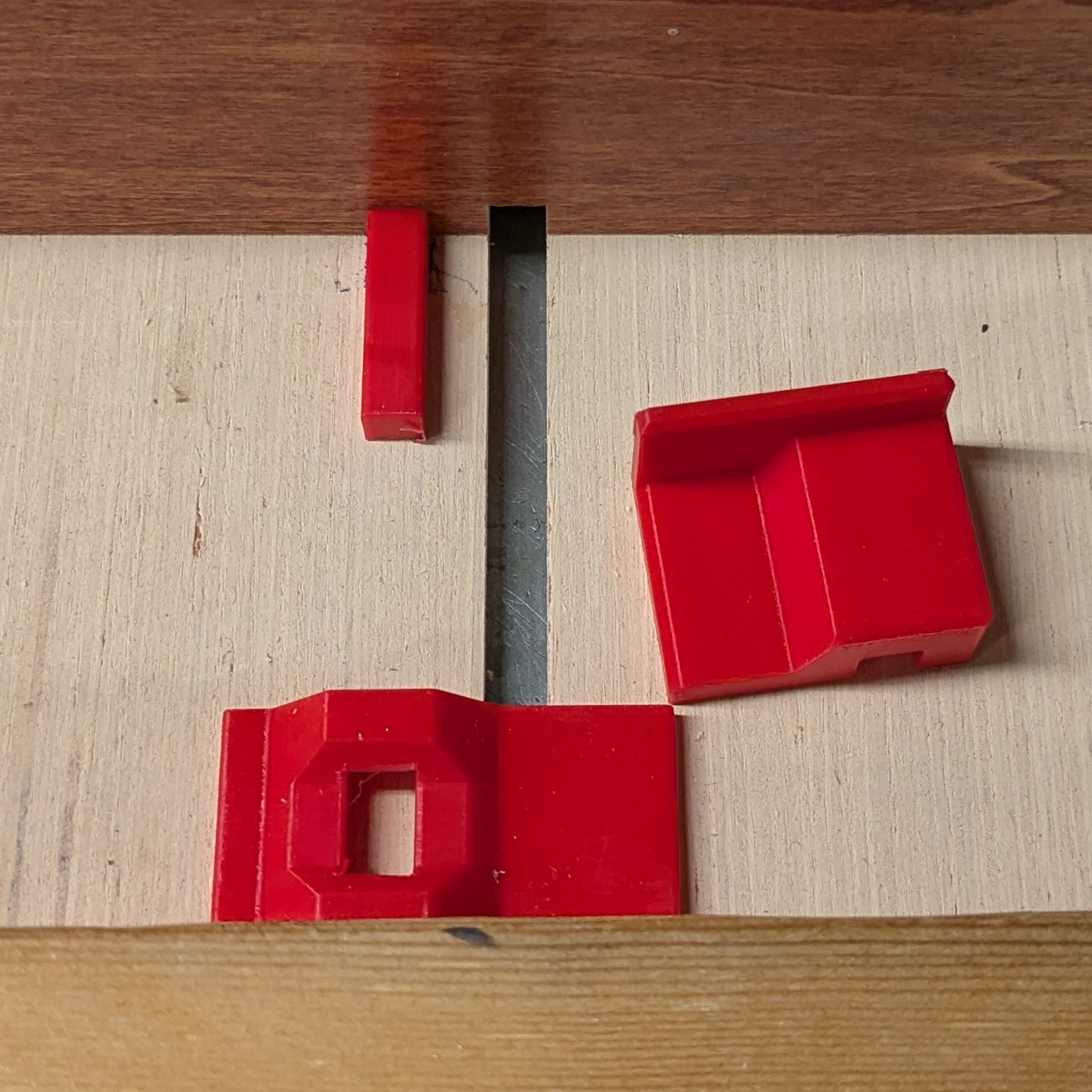
The cutout in the green allows you to hold the pin (blue) down. The flat part at the back of the first-cut spacer allows it to be clamped or held against the push plate on the sled.
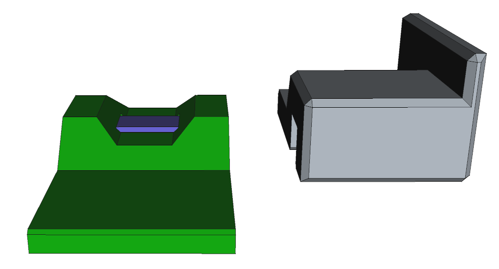
The bottom of the pin has two v-grooves running along it, with a flat region on the bottom. I applied epoxy to that flat center part. The v-grooves should keep the squeeze-out contained so that it does not interfere with the boards you actually want to cut.
My print glued and installed from ugly red PLA looks like the following images.
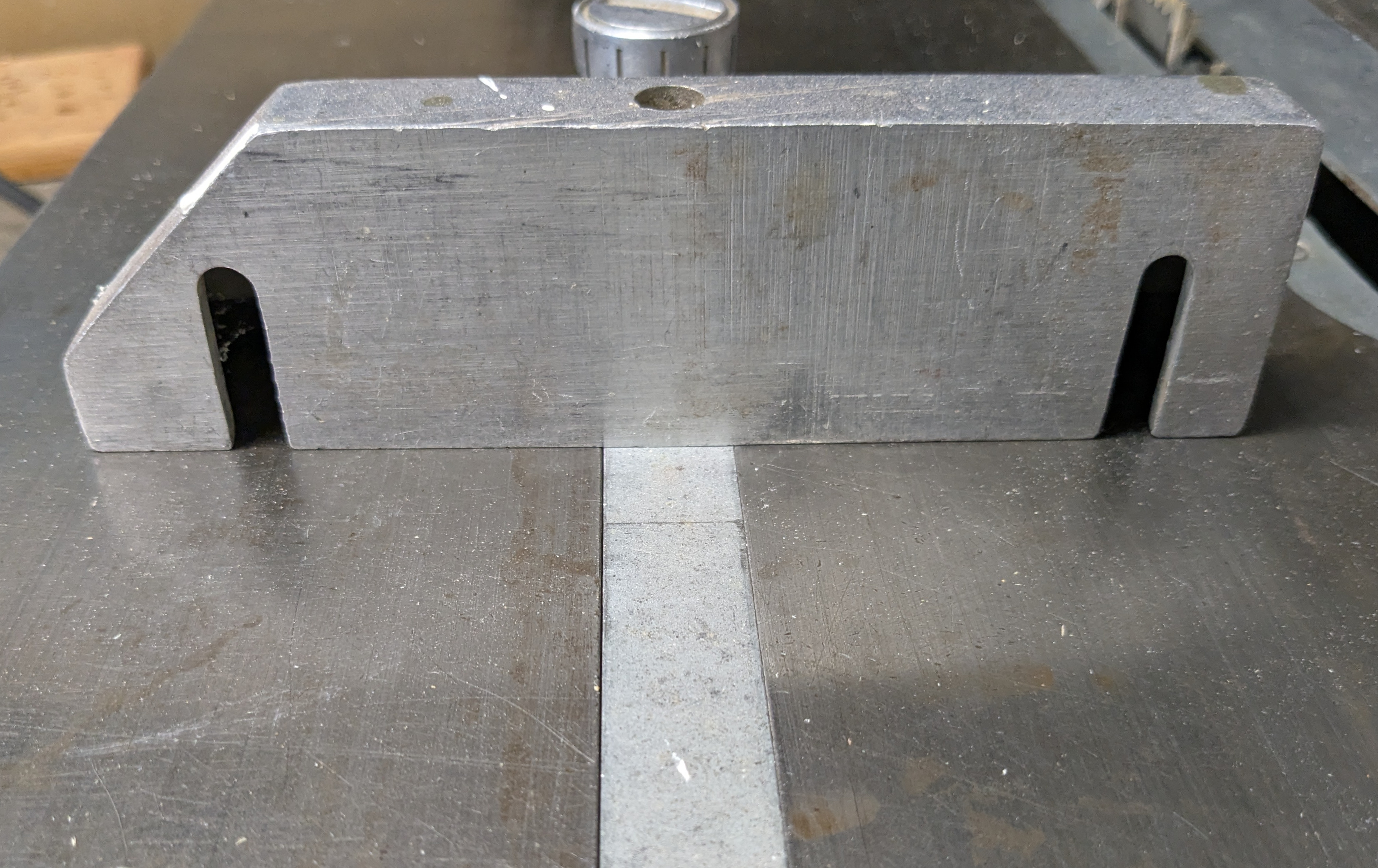
I made my cross-cut sled by cutting strips of correctly sized milled lumber that was already the same width (within scraper work) of the slot. It is the same birch board that is used as the pusher plate in the sled. I made the thickness of the tracks slightly greater than the depth of the miter slots so they would be proud of the table during glue-up. Then, I cut the thin ply strip that makes the floor of the sled. That plywood floor is deliberately chosen to be thin and to be milled sheet goods so that it doesn’t have warp or twist common in solid lumber.
I very much want the pusher board to be perpendicular to the blade. The best I can do is make it perpendicular to the miter slots, which is pretty good. I carefully measured the perpendicularity of the table top’s user-facing edge to the slots, and it is excellently square. So I wedged an aluminum bar against the user-facing table saw edge, pushed the slot guides (in the slot) up to the bar, applied wood glue, laid the plywood base and pushed it up to the bar, applied glue to the pusher, also pushing it up to the bar and weighted or clamped in place. I then glued the piece that goes along the front of the sled.
Once the glue cured, I used a hand-plane to the thin the slides until the base of the sled rested on the table across its length. I used a rectangular scraper to minimally thin any burnished areas on the slides until it slid back and forth smoothly.
As a last step to the woodwork on the sled, I mounted my dados, set the depth to match the sled base plus the material thickness plus a hair more, and cut a slot. For my table saw you have to clamp the saw height in place or it will walk during use. All this works around my horrible miter on my table saw.
Finally, I measured the slot width carefully with calipers. I measured about ten times, and used my best estimate of the average discounting measurements I could see had issues. I set the width in the parametric CAD file, printed, and used epoxy to mount the pin. The result was completely workable, and fit together flawlessly.